
Cosmic Praise rendering
This summer the big Boston project for Burning Man was Cosmic Praise, conceived and headed by Doug Ruuska, whom I mentioned earlier in this blog as instructor of the HSMWorks class and MultiCAM class at Artisans Asylum. The project consists of a 50-foot tower shaped somewhat like a minaret. A person making the climb to the top of the tower is rewarded with a working spark chamber, a device for visualizing the paths of cosmic rays.
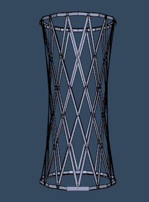
The tower structure itself is composed of three sections. The top and bottom are bolted together trusses of rectangular steel tube. The middle is made of 2” by ¼” steel strips, bolted together in a sort of basket-weave pattern. Here is a CAD model of the middle section (click to rotate and zoom):
Because the strips are placed diagonally around the cylindrical shape, they have some twist to them, around 70 degrees over their 12’7” length. How to create this twist was the question. Twisting the entire strip cold was difficult to do uniformly, and also quite dangerous because of the large spring force that would be created.
One of the most common suggestions was to heat the strips with a torch, but this also would have been difficult to do uniformly with our limited equipment. We were also worried that if we heated the entire length of the strip, it would sag in the middle.
Finally, I came up with the idea of a strip twister jig which would entail a slotted die, rotating within a length of pipe as a bearing. The slotted die could be indexed to twist the strip by a precise angle, and the operation could be repeated over short lengths of strip to avoid having to twist the whole angle at once. Here’s a 3D model of the jig as it was going to be used (click to rotate and zoom):

The whole thing was made for the cost of a few lengths of pipe. Doug had some 3” steel stock that I used to make the die. First I cut it in half (approximately) with a portable bandsaw, then flattened the cut faces, milled the slots in the halves, and pinned them together with ¼” rod. We used a piece of Schedule 80 steel pipe, which conveniently has an I.D. of 2.9”. I welded it to a pair of 1” pipes which ended up getting welded to the table.


Overall, the thing worked like a charm. I was able to reliably twist the strips in 2’ increments of 12 degrees. I used a 1” shaft approximately 3’ long as a handle. See the middle image below for how it was actually used (in a very messy productive shop).


One thing to note is that the original design for the strips called for them to be 3/8” rather than ¼” thick. This was something Doug chose because he figured it would make twisting that much easier. In this, I think he was right. Twisting these took pretty much my entire weight on the lever. The torsion constant for a rectangular bar is proportional to the cube of the short side, so going up to 3/8” would have increased the required torsion force by 3.375. It would have taken a team of people hanging on the lever to twist that. As it is, the ¼” strips were later reinforced with welded-on flanges. This was a nightmare for those who had to do all those welds but made it much easier to do the twisting.