Last month, I took an intro to HSMWorks at Artisans Asylum. HSMWorks is an add-on CAM package for SolidWorks. CAM (Computer Aided Machining) refers to software that forms the bridge between a CAD model and the numerous CNC machines that we have at the Asylum. It allows a user to specify the machining operations needed to cut out a part, and then simulate the operations to verify how well the result will match the original model.
Learning HSMWorks is a prerequisite for being able to use the MultiCAM router, but its output will also work with the Matsuura 3-Axis VMC, and other CNC devices at the Asylum. HSMWorks has recently been acquired by Autodesk, who integrated it into their own Inventor and Fusion CAD products while continuing to support the SolidWorks version. As a result, HSMWorks appears to have a bright future, and it’s one of the most capable and easy-to-use CAM packages.
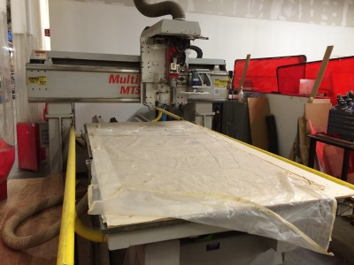
The MultiCAM router
Teaching the class was Doug Ruuska, a veteran machinist, maker and guardian of the MultiCAM. The MultiCAM is a powerful but finicky machine: in minutes it can turn a ½” thick 4’x8’ sheet of plywood into flat-pack furniture, or turn itself into scrap metal. And Doug has every incentive to keep the machine running – not only is he one of its co-owners, but he uses it for many of his own projects that can be seen at Burning Man and its local offshoots.
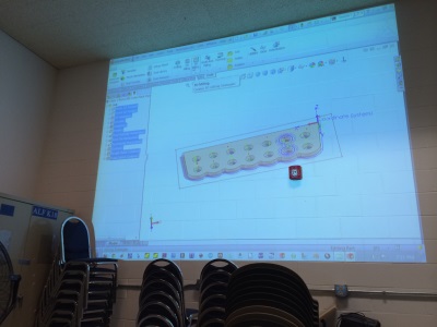 Collet holder |
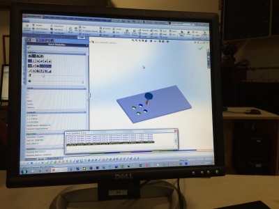 Comparing hole cutting methods |
In the first week, we went over some of HSMWorks’ menu structure and practiced creating toolpaths for a simple collet holder made from plywood. The primary objective of the class was to compare the different strategies that HSMWorks can use for cutting something as simple as a round hole. These different strategies have pros and cons such as speed, wear on the cutting tool, and quality of the finished surface.
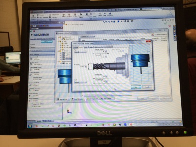
Creating a custom tool
The second week introduced the HSMWorks tool library which allows the user to select which cutting tool to use for a particular operation, as well as define new ones. We practiced entering new tools from a catalog, and comparing their effects in simulations.
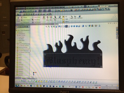 The sign we were making |
 A simulation of cutting a letter in multiple steps |
In the third week, we tried our hand on a moderately-complex part, a sign with letters cut into it. There were several tricks to doing this, because a larger tool won’t fit into the corners of the letters, but a smaller tool would take too long. So we played with a multi-step process where we roughed out the larger volumes and then went back with progressively finer tools.
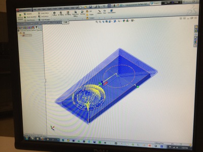
Toolpaths on a three-dimensional object
In the last week, we approached operations for cutting out 3D shapes, a considerably more complex process. Much more material typically has to be removed, so roughing passes are necessary. When cutting 2D shapes, a flat-bottomed cutting tool will leave a flat surface. But when cutting curved surfaces, the bottom of the tool will not have the same shape as the surface, so the the choice of cutting tool and toolpath has a huge impact on the final quality of the surface. Doug showed some tricks that will lead to a faster and more accurate machining process.
For me, this class was a stepping stone, since my ultimate goal is to use the MultiCAM, but on its own it introduced me to some of the subtleties of modern CNC machining. The software has its quirks but it’s vastly more intuitive and easy-to-use than some of the free alternatives like CamBam that I’ve been exposed to.